EncoderCAT - images of G3VPX prototype unit
My EncoderCAT unit is housed in a box constructed from 1.6 oz double-sided copper clad PCB material.
I find this to be a versatile and easy to use construction material.
- Easy to cut and shape
- Panels are soldered together and quite complex 3 dimensional arrangements are possible.
- see http://www.g3vpx.net/picastar/box.htm - Mounting brackets are simply soldered to the box sides
- see image - brass angle lid mounts (heat needed - preferably before you paint the box!)
Note: If you make a full length solder fillet between two otherwise unsupported panels, then
the joint will become angled as the solder cools.
- Therefore the whole box should initially be assembled with small solder tacks.
- Then you can then fully fillet-solder the joints without risk of distortion.

|
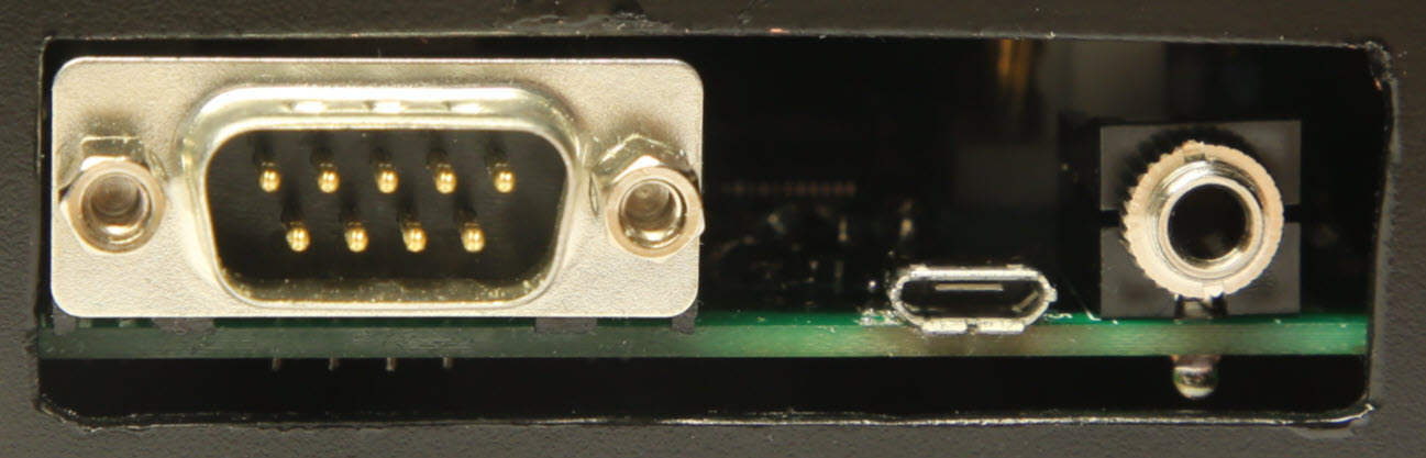
Rear connectors 3.5 mm mono jack socket for Icom CI-V In this development unit, I made a hole large enough to easily route in the temporary JTAG programming cable. |
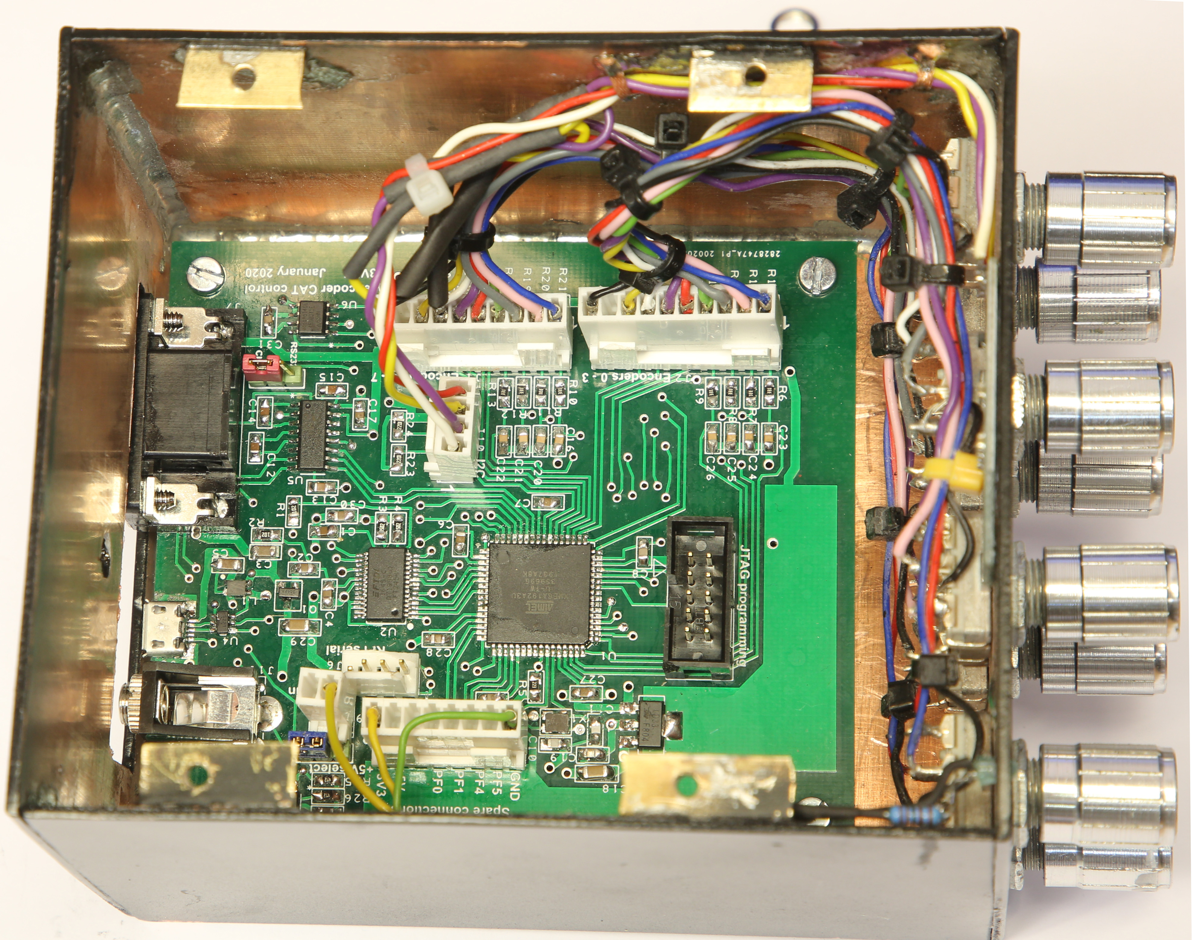
EncoderCAT - prototype - internal views - image
The PCB mounting points connect the ground pane to the box via 3mm threaded brass pillars.
A 3mm front panel power indicator LED and series resistor are driven by the 'spare' connector.
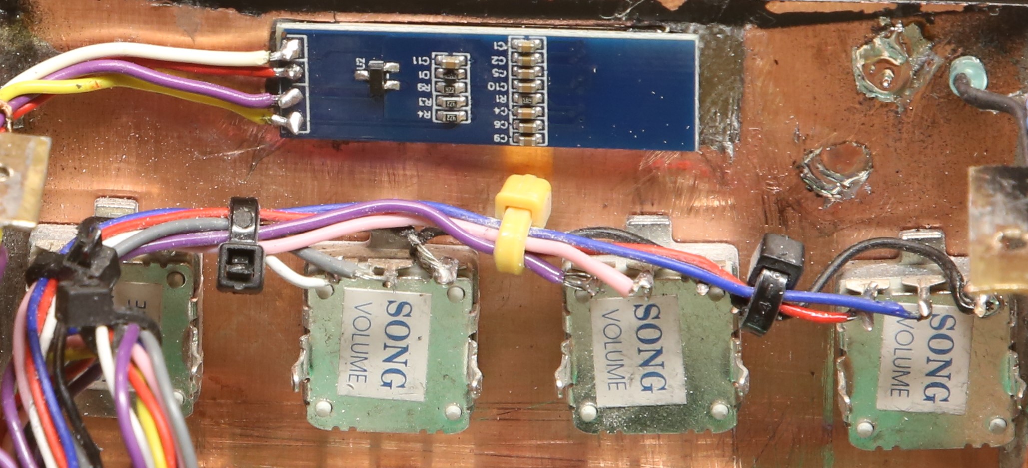
Rotary encoders and OLED display - image
Below is a close up of the OLED display panel and some encoders.
These encoders are Song volume controls ... but there are alternative suitable similar devices.
The encoders have common terminal (in this case: on the right) which is connected to ground.
I have referred to the other two encoder connections as phase and quad.
When the encoder is in a rest state (ie: sitting in a mechanical notch) then phase and quad are open circuit.
If the encoder is moved right or left, phase and quad are briefly grounded .. but not simultaneously.
Their contacts are offset from each other such that:
- Grounding phase triggers a processor interrupt.
- The firmware interrupt service routine checks the phase lines to identify the triggering encoder.
- It then examines the associated quad line to determine the direction of rotation.
It is possible to leave an encoder stuck between notches. The firmware has code to ensure that this does
not inhibit the operation of a different encoder.
The OLED display is glued to the rear of the front panel with impact adhesive.
It has a 4 - wire I2C cable from J10 on the PCB. ( 0v, 3v3, SDA and SCL )
The copper under the four connections was filed away to avoid short circuiting.